Arduino Nano I2C Pins : How To Connect Multiple I2c Devices To Arduino Nano Quora - The board comes in two options:
Get link
Facebook
X
Pinterest
Email
Other Apps
Arduino Nano I2C Pins : How To Connect Multiple I2c Devices To Arduino Nano Quora - The board comes in two options:. Connect the red jumper cable from the vcc pin on the lcd to the vcc pin on. If you are using any other board then the following table will be useful to you as it describes the i2c pins on all the popular arduino boards. I am trying to create an i2c communication bus with an arduino uno. It comes with an even more powerful processor atmega4809 (20mhz) and a larger ram capacity of 6 kb (3 times). In order to make them work , be sure to include the wire.h library.
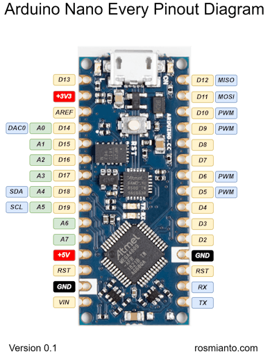
Sda is the serial data pin and scl is the clock pin. I got some arduino nanos at really good price on amazon and wanted to connect a 7 segment led display with an i2c backpack. On the arduino boards with the r3 layout (1.0 pinout), the sda (data line) and scl (clock line) are on the pin headers close to the aref pin. (image 2) connect both a4 analog pins together, these pins are sda, or data transfer pins. It offers the same connectivity and specs of the arduino uno board in a smaller form factor.
Arduino Nano 33 Ble Sense Arduino Official Store from store-cdn.arduino.cc The arduino software includes a wire library to simplify use of the i2c bus. Using the arduino i 2 c address scanner, it is unable to find a device, even though it is wired correctly (i've checked multiple times). I want to warn here for false documentation due to wrong pinout description for arduino nano. Connect sda to a4 pin on arduino, and scl to a5 pin: Pin19 (no label on the pcb front, only visible from the side) arduino mega. We will see all the pins section wise as well as a detailed format at last. I got some arduino nanos at really good price on amazon and wanted to connect a 7 segment led display with an i2c backpack. Pin a6 and a7 does not support pwm.
It offers the same connectivity and specs of the arduino uno board in a smaller form factor.
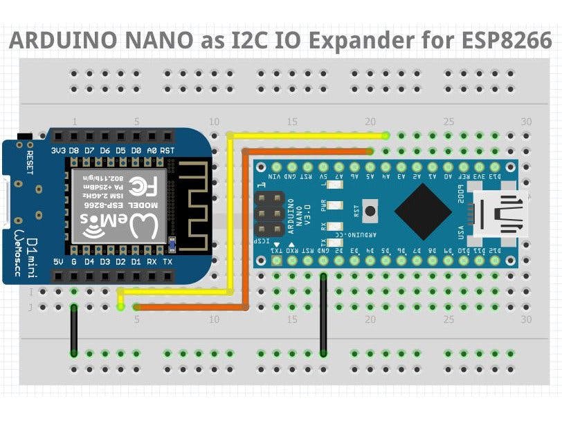
I2c requires sda and sdl pins. The arduino nano can be programmed with. Same i2c addresses devices are used; If an arduino is slave, and it has the power turned off, that will keep the sda and scl low via the diodes. Arduino nano every schematic informs us that we can use atmega4809's pins pf03 and pf02 to communicate via i2c. Can't get i2c to work on an arduino nano. I had some confusion initially but later found out that sda and scl on arduino nano are available on a4 and a5 pins. You can connect up to 8 analog/digital sensors to the board. I want to warn here for false documentation due to wrong pinout description for arduino nano. Atmega4809 manual says in page 19 that in order to use those pins as i2c we need to use. The board comes in two options: 16 pins are faced to rear side and 4 pins faced towards front side. If you like to know how you can reduce the number of input pins for a keypad from 8 to only 2 i2c pins, with the help of the i2c multiplexer, then visit the keypad tutorial for arduino, esp32 and.
Using the arduino i 2 c address scanner, it is unable to find a device, even though it is wired correctly (i've checked multiple times). 16 pins are faced to rear side and 4 pins faced towards front side. Can't get i2c to work on an arduino nano. I am trying to create an i2c communication bus with an arduino uno. If you like to know how you can reduce the number of input pins for a keypad from 8 to only 2 i2c pins, with the help of the i2c multiplexer, then visit the keypad tutorial for arduino, esp32 and.
Nano I2c Io Expander Arduino Project Hub from hackster.imgix.net Normally i2c devices are connected through a bus. Pin a6 and a7 does not support pwm. Fill your cart with color today! On the arduino boards with the r3 layout (1.0 pinout), the sda (data line) and scl (clock line) are on the pin headers close to the aref pin. To use the spi communication, please see atmega328 datasheet. (image 2) connect both a4 analog pins together, these pins are sda, or data transfer pins. I just receive my nano board(s) today and the first thing i wanted to do was map out and explore the i2c sensors on board. Then i tried running the standard i2c_scan demo sketch and still nothing.
1 value = analogread (pin, value);
Atmega4809 manual says in page 19 that in order to use those pins as i2c we need to use. This library can only be used on some specific pins of the board, those pins are called scl and sda, on the arduino nano family boards, the sda (data line) and scl (clock line) are on. Interface i2c 16x2 lcd with arduino uno. Atmega328p microcontroller used in arduino uno. It offers the same connectivity and specs of the arduino uno board in a smaller form factor. That i2c bus is connecte. The 2 first pins side to usb connector are sda/scl according to documentation. Host controllers for connecting your pc to i2c bus and spi devices. It is also known as i2c module. To connect 16×2 lcd display to arduino we use i2c pcf 8574t module. Pin19 (no label on the pcb front, only visible from the side) arduino mega. I see on arduino uno there is twice sda and sdl: Do not use the d4/d5 pinout!
It offers the same connectivity and specs of the arduino uno board in a smaller form factor. Arduino uno has 6 analog pins, whereas nano has eight analog pins numbered from a0 to a7. Connect the black jumper cable from the gnd pin on the lcd to the bnd pin on the nano. As a reference the table below shows where twi pins are located on various. You can connect up to 8 analog/digital sensors to the board.
Pin Out And Information About Nano Every Nano Every Arduino Forum from hackster.imgix.net (image 2) connect both a4 analog pins together, these pins are sda, or data transfer pins. I wasted a lot of time using the wrong ports. 16 pins are faced to rear side and 4 pins faced towards front side. You probably think (as i did and as the guys laying out the pinout diagrams) that these would be on digital pins, but they are not. It comes with an even more powerful processor atmega4809 (20mhz) and a larger ram capacity of 6 kb (3 times). Connect sda to a4 pin on arduino, and scl to a5 pin: One of the cheapest and most widely used one is the pcf8574/pcf8574a. A softwareserial library allows for serial communication on any of the nano's digital pins.
The i2c pins a4/a5 (or sda/scl) are in use already for other purposes;
Atmega328p microcontroller used in arduino uno. The pinout for nano rp2040 connect. Do not use the d4/d5 pinout! This project will read the position of a potentiometer connected to a master arduino, send the information over i2c, and change the blink rate of the led on the slave arduino. We can infer from the image that arduino nano got 36 pins in total. The nano has two more analog pins, however. The arduino nano pins, similar to the uno, is divided into digital pins, analog pins and power pins. The arduino has both i2c and spi pins, and there are a number of i2c and spi gpio chips, and modules built with those chips. Connect the black jumper cable from the gnd pin on the lcd to the bnd pin on the nano. This makes i2c communication very accessible on the arduino and the examples are good enough for the first experiments. Fill your cart with color today! 1 value = analogread (pin, value); If you like to know how you can reduce the number of input pins for a keypad from 8 to only 2 i2c pins, with the help of the i2c multiplexer, then visit the keypad tutorial for arduino, esp32 and.
For arduino uno boards, these are pins a4 arduino nano. It offers the same connectivity and specs of the arduino uno board in a smaller form factor.

Comments
Post a Comment